Introduction
Newton is a 2D physics simulator for Adobe After Effects (AE).
Newton interprets 2D layers of the current composition as rigid bodies in a physical world. These bodies can collide with each other, slide, bounce, and react to gravity. Bodies can also be connected using joints.
Newton supports various types of bodies: some types allow bodies to be animated in AE while reacting to physical forces, and others are entirely controlled by the solver.
Newton provides a simple, clean, and easy-to-use interface, offering fast OpenGL preview and intuitive controls. Once the simulation is completed, Newton exports the animation to AE using standard keyframes.
Note:
- Newton is not an effect, and you won't find it in the Effects & Presets panel. You open it using the Newton command from the Composition menu.
Bodies
Newton transforms the 2D layers of the composition into physical objects called bodies. These bodies can bounce, slide, and collide with each other.
Newton ignores the following layer types: audio layers, guide layers, 3D layers, and video-disabled layers.
When creating a scene in AE it is important to keep in mind that Newton doesn't look at layer pixels, it only interprets the shape/contour of a layer. For instance, precomp or footage layers will be interpreted as rectangles, no matter what they contain or represent. Every custom body shape must be created with masks, shapes, or text.
To change the properties of a body, you must first select it in the body table or directly in the preview. Body settings can be copied from one body and reapplied to other bodies using the Copy/Paste Body Settings commands in the Edit menu.
Notes:
- When a layer has multiple masks or when a shape layer contains multiple shape groups, you will be prompted to choose whether you want to separate these shapes into individual bodies (see Separating Shapes).
- Complex shapes may be represented by a mesh with hundreds of polygons, and performances may suffer. Keep custom shapes as simple as possible (using a proxy shape for instance), or use the convex hull option (see Use Convex Hull) to reduce unnecessary precision.
- Illustrator footage layers can be converted to shape layers using the Create Shapes from Vector Layer command.
General Properties
The general body properties concern internal body settings such as the body type, the friction coefficient, or the restitution (bounciness) factor.
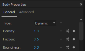
Type
Newton supports the following body types:
- static: a non-moving body
- kinematic: a body animated in AE with keyframes or expression; its motion path is not altered by the physics until the end of the animation (i.e., the last keyframe time or the end of comp when animated by expression), where the body becomes dynamic
- dynamic: a body fully controlled by the solver (default type)
- dormant: a body not influenced by gravity until another body collides with it, and makes it dynamic
- AEmatic: a body animated in AE with keyframes or expression, but also influenced by the physics (hybrid type between kinematic and dynamic types)
- dead: a body ignored by the solver (in terms of collision response)
- triggermatic: a dormant body until its sensor has detected a collision which triggers its animation (as defined in AE)
Density
This parameter defines the mass of a non-static body. High-density body doesn't fall faster than a low-density body (they fall at the same speed), however when a collision occurs the difference is easily noticeable.
Friction
This parameter influences the way bodies slide along each other. A value of 0 turns the friction off, and a value of 1 makes the friction strong.
Bounciness
This parameter is used to make bodies bounce. A value of 0 means no bounciness (e.g., a ball falling on the ground will not bounce), and a value of 1 means high bounciness (e.g., a ball falling on the ground will bounce indefinitely).
Color
This parameter sets the body color used in the simulation preview.
Mesh Precision
This parameter is used by Newton's internal shape triangulator when a body is defined by a shape with round corners. The default value is 2. A higher value increases precision but performance may suffer. For complex shapes, it is highly recommended to keep this value as low as possible.

Velocity Magnitude/Direction
These parameters can be used to set the linear velocity of a body. You can also set the velocity vector directly in the preview using the Velocity tool (P).
Note:
- When you move the velocity handle, you can see the body's trajectory.
Angular Velocity
This parameter is used to set the angular velocity of a body.
Linear Damping
This parameter is used to reduce the linear velocity of a body.
Angular Damping
This parameter is used to reduce the angular velocity of a body.
AEmatic Damping
This parameter is used only by AEmatic bodies. It corresponds to the damping coefficient of the joint connecting the motion path set in AE (desired path) and the motion path determined by the solver.
AEmatic Tension
This parameter is used only by AEmatic bodies. It corresponds to the tension of the joint connecting the AE motion path and the motion path determined by the solver.
Note:
- You can move the anchor of the AEmatic connection using the Anchor tool (Y).
Trigger > Sensor
This parameter defines the body that acts as a sensor for a triggermatic body. When a collision occurs with the sensor the triggermatic body starts its animation (as defined in AE). You can select a sensor body either by using the dropdown list or by directly picking a body in the preview with the Trigger Sensor Sampler tool.
Trigger > Loop Type
This parameter determines the loop type of the triggered animation. You can choose between Cycle (after contact, the body starts its animation and goes back to its initial state), Pingpong (after odd/even contact, the body starts its animation in the original/reversed direction), Offset (after contact, the body starts its animation from the last state), and Continue (after contact, the body moves according to the animation of the last two keyframes).
Hidden
This parameter sets the visibility of the selected bodies. When a body is hidden, it is not shown in the preview but it is not ignored by the solver and participates in the simulation.
Advanced Properties
The advanced body properties concern optional settings that allow you to control additional aspects of a body, such as collision filtering or magnetism.
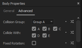
Collision Group, Collide With
You can assign a collision group to a body (five groups are available), and specify which groups the body should collide with. By default, all bodies belong to the same group and can collide with every other group.
Fixed rotation
This parameter is used to prevent body rotation.
Gravity Scale
This parameter allows you to set a custom gravity per body. A value of 0 turns gravity off for the body.
Note that negative values are allowed.
Use Convex Hull
This parameter allows you to approximate the geometry of a complex body using the convex hull of the shape vertices. In some situations, when working with text, for instance, this option can highly increase performance while producing realistic simulations.

Export Contacts
This parameter allows you to export every contact for a body as a keyframe in AE. A slider effect called Contacts is added to the layer to hold contact keyframes.
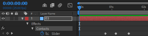
This can be used to synchronize events, for instance starting a precomp at each contact keyframe.
Note:
- See the Export Contacts sample projects for examples of how to use contact keyframes with expressions.
Magnetism > Type
This parameter allows you to transform a body into a magnet that can either attract or repulse other bodies.
Magnetism > Intensity
This parameter specifies the intensity of magnetism.
Magnetism > Distance
This parameter determines the maximum distance at which the magnet is active.
Magnetism >Accept
This parameter specifies whether the body is sensitive to the magnetism of other bodies.
Waterlike > Enable
This parameter allows the simulation of a buoyancy effect. The other bodies are pushed in the opposite direction to gravity when they penetrate the waterlike body.

Waterlike > Density
This parameter sets the density of a waterlike body. Low value allows the other bodies to pass through the water without being affected, high value makes them bounce against the surface. The density of the bodies penetrating a waterlike body also influences the buoyancy effect.
Waterlike > Drag Factor
This parameter acts as a multiplier for the drag force. The drag force is applied to the bodies in the opposite direction to their current movement.
Waterlike > Lift Factor
This parameter acts as a multiplier for the lift force. The lift force is applied to the bodies in a direction perpendicular to their current movement.
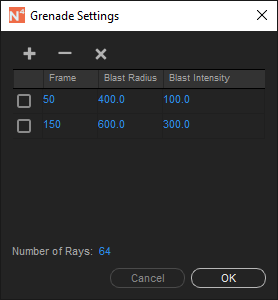
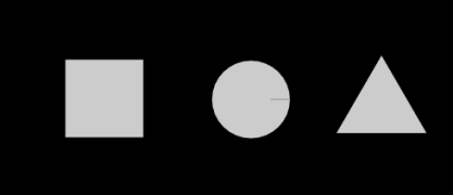
Grenade
This parameter enables the grenade behavior for the selected bodies. The grenade effect simulates an explosion that pushes surrounding bodies away from the blast location.
Explosion parameters (blast time, blast radius, blast intensity, and the number of explosion rays) can be set using the Grenade Settings dialog.
Notes:
- The grenade option can only be applied to simple shapes such as circles, rectangles, or triangles.
- When you select a grenade body, explosion rays are shown in the preview to help visualize the bodies that will be impacted by the explosion.
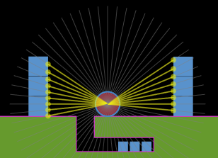
Grenade ray casting
Teleportation > Teleportable
This parameter specifies whether the body accepts teleportation.
Teleportation > Trigger
This parameter indicates whether the body is teleported when the contact with a portal begins or when the contact ends.
Teleportation > Destination
This parameter sets the teleport destination body to which the body is teleported. You can select a sensor body either by using the dropdown list or by directly picking a body in the preview with the Teleport Destination Sampler tool.
Note:
- When you select a Teleport Destination body, it is often desirable to adjust the Collision Group and the Collide With parameters so that the teleported body doesn't collide with the destination body.
Teleportation > Destination Position
This parameter specifies which position Newton should choose for the destination body. You can select either Initial (the destination body's position at its in point) or Current (the actual destination body's position when the teleportation occurs).
Teleportation > Linear Velocity
This parameter controls the linear velocity of the teleported body. You can choose between Initial (the initial body's velocity as defined by the Velocity Magnitude and Velocity Direction parameters), Current (the body's velocity when the body is teleported), From Destination - Initial (the initial velocity of the destination body), or From Destination - Current (the current velocity of the destination body).
Teleportation > Angular Velocity
This parameter is similar to the Teleportation > Linear Velocity parameter but it acts on the angular velocity of the teleported body.
Teleportation > Velocity Factor
This parameter allows you to scale the velocity (linear and angular) of the teleported body. Negative values are also permitted.
Teleportation > Rotation
This parameter specifies the rotation of the teleported body. You can choose between Initial or Current.
Teleportation > Portal
This parameter allows the body to behave as a teleportation portal. The bodies passing through the portal are teleported to their destination.
Teleportation > Portal Destination
This parameter specifies the body to which the portal teleports the bodies. You can choose between From Teleported (i.e., the destination is taken from the selected destination for the teleported body), or select a specific body in the scene.
Teleportation > Portal Inverts Angular Velocity
This parameter allows a portal to change the sign of the angular velocity of a teleported body.
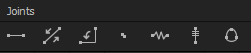
Joints
Newton allows you to create joints between bodies. A joint is used to add a constraint between two bodies.
To add a new joint, select two bodies and use one of the Add Joint buttons above the joint table. To remove a joint, select it in the table (or press W when one of the connected bodies is selected), and click on the Remove Joint button (or press Alt W). To modify joint properties, you must first select the joint, and then change its properties.
Each type of joint has an Active parameter that allows you to activate or deactivate the joint. This parameter can be animated to create a dynamic joint.
Joint settings can be copied from one joint and reapplied to other joints of the same type using the Copy/Paste Joint Settings commands in the Edit menu or in the joints table context menu.
Notes:
- Use the Anchor tool (Y) to reposition joint anchors.
- When multiple bodies are selected, multiple joints are created at once (see keyboard shortcuts section for details). The order of selection is important when creating multiple joints. Use the Shift key while clicking on the bodies to create an ordered selection (e.g. for creating a chain of bodies).
- You can customize the appearance of joints (colors and stroke width) in the Preferences dialog.
Distance Joint
A distance joint implies that the distance between two points (joint anchors) on two bodies must be constant. This is not always true since you can give elasticity to the joint, and obtain a soft distance joint.

Tension
This parameter allows you to give elasticity to the joint. This can be used for instance to create a soft body (by connecting several small bodies with soft distance joints).

Damping
This parameter is used to reduce or soften the amount of motion.
Collide Connected
This parameter specifies whether the two connected bodies should collide with each other.
Piston Joint
A piston joint allows for the relative translation of two bodies along a specified axis. Their relative rotation is fixed. Its parameters are similar to the pivot joint parameters, except that rotation is replaced with translation. The translation axis must be set directly in the preview using the Joint Anchor tool (Y). When the motor is enabled the joined bodies try to move at a given speed, with a given force.
Enable Limit
This parameter is used to force the joint translation to remain between a lower and upper bound.
Lower Translation
This parameter specifies the lower bound of the joint translation.
Upper Translation
This parameter specifies the upper bound of the joint translation.
Enable Motor
This parameter determines whether the joint motor is enabled.
Motor Speed
This parameter allows you to specify the joint motor speed.
Max Motor Force
This parameter allows you to specify the maximum motor force allowed.
Collide Connected
This parameter specifies whether the two connected bodies should collide with each other.
Pivot Joint
A pivot joint forces two bodies to share a common anchor point or pivot point. The joint angle is the relative rotation between the two bodies and can be restricted to a specific range. The pivot point must be set directly in the preview using the Joint Anchor tool (Y).
Enable Limit
This parameter is used to force the joint angle to remain between a lower and upper bound.
Lower Angle
This parameter specifies the lower bound of the joint angle.
Upper Angle
This parameter specifies the upper bound of the joint angle.
Enable Motor
This parameter determines whether the joint motor is enabled.
Motor Speed
This parameter allows you to specify the joint speed.
Max Motor Torque
This parameter allows you to specify the maximum motor torque allowed.
Collide Connected
This parameter specifies whether the two connected bodies should collide with each other.
Weld Joint
A weld joint allows you to glue two bodies together. The tension parameter can be used to introduce some flexibility in the joint. It is similar to the distance joint except that it acts on the relative rotation between the two bodies rather than distance.
Tension
This parameter allows you to give flexibility to the joint. At the default value (i.e., 0), the two bodies are strictly glued together.
Damping
This parameter is used to reduce or soften the amount of motion.
Collide Connected
This parameter specifies whether the two connected bodies should collide with each other.
Spring Joint
A spring joint constrains two bodies to move like they were connected by a spring.
Springiness
This parameter controls the strength of the spring.
Damping
This parameter allows you to reduce the amplitude of oscillations.
Desired Length
This parameter specifies the length of the spring when it is inactive.
Wheel Joint
A wheel joint is a mix between a piston and a pivot joint. This joint is typically used to attach a wheel to a vehicle. It provides suspension and has a motor. The translation axis must be set directly in the preview using the Joint Anchor tool (Y).
Note:
- The order in which you select the bodies is important when creating a wheel joint. You need to select the vehicle first, then the wheel body. See Car and Motorbike sample projects for examples of how to set up wheel joints.
Suspension
This parameter controls the spring suspension.
Damping
This parameter allows you to reduce the amplitude of oscillations.
Enable Motor
This parameter determines whether the joint motor is enabled.
Motor Speed
This parameter allows you to specify the joint motor speed.
Max Motor Torque
This parameter allows you to specify the maximum motor torque allowed.
Collide Connected
This parameter specifies whether the two connected bodies should collide with each other.
Blob Joint
A blob joint forces a group of bodies to maintain a constant volume within them (actually a constant area since we are in 2D). Internally, the blob joint uses several soft distance joints to connect the bodies.
Tension
This parameter allows you to control the softness of the joint.
Damping
This parameter is used to reduce the amount of motion.
Collide Connected
This parameter specifies whether the connected bodies should collide with each other.
User Interface
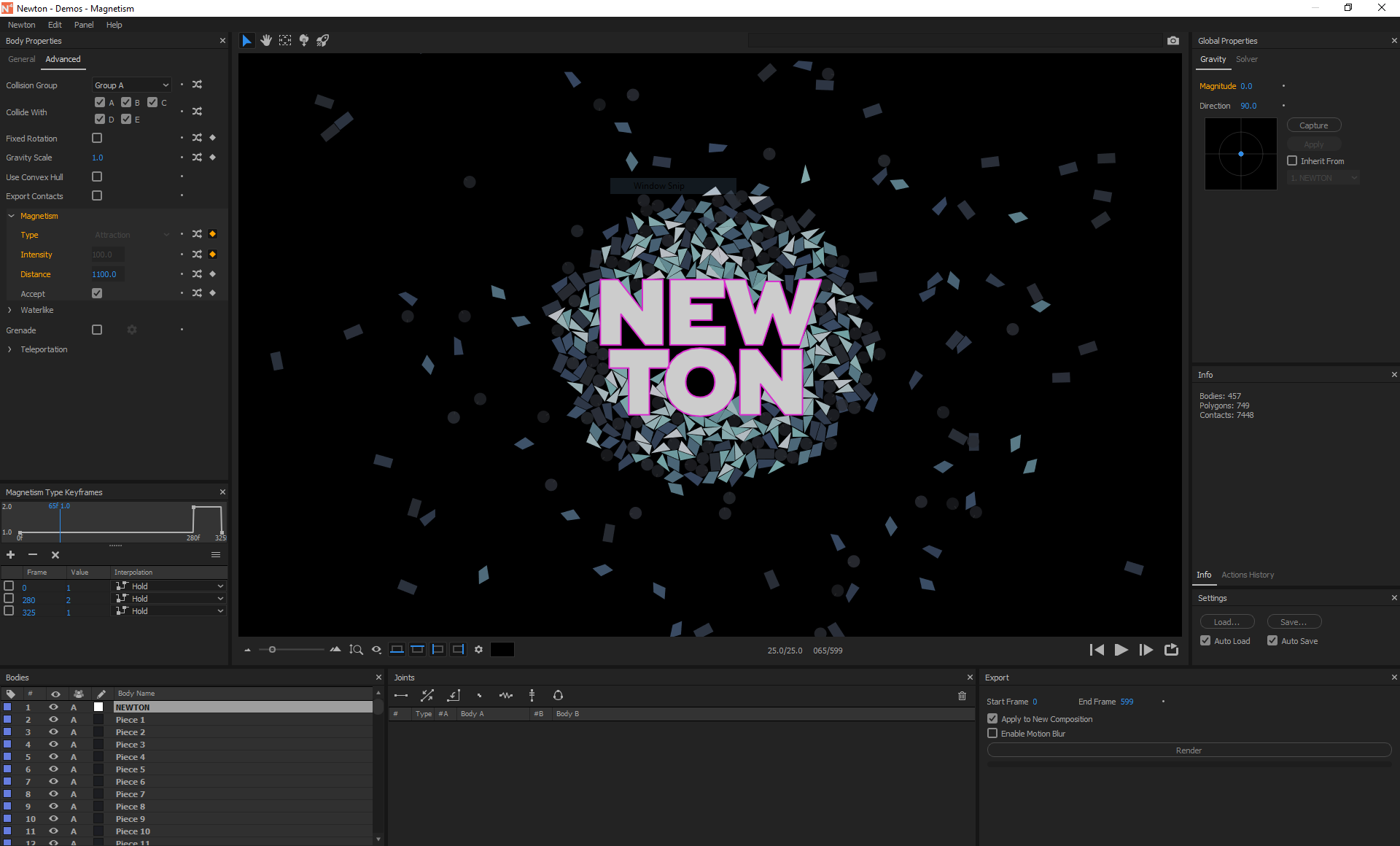
Newton offers a clean cross-platform interface that is used to create the scene setup.
Preview
Newton provides an OpenGL view to preview the result of the simulation. The view handles mouse and keyboard events. For instance, you can zoom and pan in the view, or select and move bodies in the scene. A contextual menu also provides some common operations (accessible from both the preview and the body table).
Preview Options
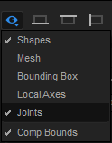
The following visualization options are available in the View Options popup menu:
- Shapes: displays all shapes
- Mesh: displays internal shape representation (Newton uses the poly2tri library to triangulate shapes)
- Bounding Box: displays axis-aligned bounding box
- Local Axes: displays local X and Y axes, in red and green respectively
- Joints: displays all joints
- Comp Bounds: displays a thin frame that indicates the bounds of the composition
Tool Buttons
There are five tool buttons above the preview, each one being used for a specific operation:
- Selection (V): to select bodies and move them
- Hand (H, space bar, or middle mouse button): to pan the view
- Anchor (Y): to modify joint anchors
- Gravity (G): to set gravity directly in the preview
- Velocity (P): to set body velocity directly in the preview

Notes:
- You must select at least one joint (or an AEmatic body) before using the Anchor tool.
- You must select at least one body before using the Velocity tool.
- When the Velocity tool is selected, holding down Alt when you click on a body allows you to select it.
Zoom
You can zoom in and out of the preview by using either the zoom slider, the mouse wheel, or the dedicated buttons. The Best Fit Zoom button allows you to automatically scale the scene to fit the view.

Background Color
By default the background color of the preview is the same as the background color of the composition. You can change it by using the color picker next to the zoom slider.

Simulation Commands
To start the simulation, click on the Play button (shortcut key: 0). The other available commands allow you to restart (shortcut key: Enter (Numpad) or Home), step one frame (shortcut key: 1 or PageDown), and activate the loop mode (shortcut key: 2).

Wall Buttons
It is sometimes desirable to make composition bounds act as static walls. To this end, Newton offers the ability to automatically create a bottom, top, left, or right wall that can be activated using the corresponding button below the preview. The composition walls can also be used as teleportation portals.

Notes:
- You can modify the default wall settings (friction, bounciness, infinite wall, ...) using the Comp Wall Settings dialog accessible via the small gear icon next to the wall buttons.
- The One-Sided Wall parameter allows the bodies to pass through the comp walls when they come from outside the comp.
- The Teleportation Portal parameter converts the walls to portals that teleport the bodies when they pass through the walls. The destination is controlled by the Teleport Destination parameter. You can choose between Looping World (the bodies are teleported to the opposite side), or From Body (the destination position is controlled by the corresponding setting of the teleported bodies).
Scene Snapshots
The Take Scene Snapshot button above the preview allows you to save temporarily the current scene settings as a preset. To restore a Scene Snapshot, double-click on it. You can delete it by using either the context menu of the snapshots list (right-click > Delete), or the delete/backspace key. This feature is useful for creating multiple versions of the same scene without having to export separate settings files for each one.

Context Menu
A context menu regrouping some common operations is available by right-clicking in the preview. This context menu is also attached to the body table.
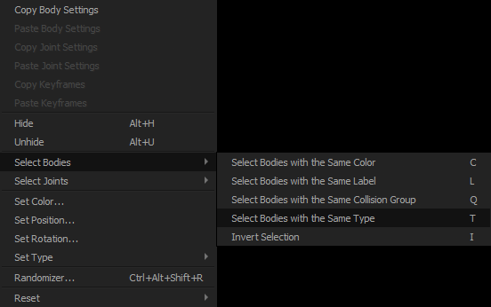
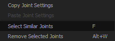
The joints table also provides a context menu.
The Randomizer command opens the Randomizer dialog. It allows you to generate a random value for a given property. With some bodies or joints selected, open the Randomizer, then select a property in the list and specify the range of the random values.
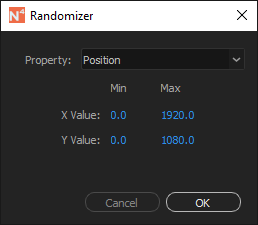
Note:
- To open the Randomizer dialog you can either use the Randomizer command in the contextual menu (by default the position will be selected in the dialog) or click on the Randomize button next to a specific property (the property will be directly selected in the dialog).
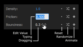
Property Anatomy
Property value can be set either by directly typing the desired value in the edit box or by dragging the value horizontally (similar to AE's scrubby sliders).
Next to almost every property, you will find the following buttons:
- Reset: to reapply the default value
- Randomize: to open the Randomizer dialog with the property selected
- Keyframe: to open the Keyframe panel
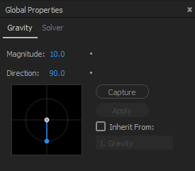
Gravity
Gravity is a force acting on all bodies. You can set its magnitude and direction using either the edit fields, the gravity view, or the Gravity tool (G). You can animate the gravity by capturing mouse movement, or using the Inherit From checkbox that allows you to select a composition layer (the layer's position will be used as the gravity vector).
Note:
- The gray circular guide indicates a magnitude of 10.
Magnitude
This parameter specifies the magnitude of the gravity vector.
Direction
This parameter specifies the direction of the gravity vector. When changing the gravity in the gravity view or with the Gravity tool, hold the Shift key to snap the vector to the nearest axis (horizontal or vertical).
Inherit From
Use this option if you want gravity to inherit its value from the position of a layer. For instance, position [0,10] represents the default gravity which has a magnitude of 10 and a direction of 90°.
Capture, Apply
When Capture is active, every mouse movement in the gravity view is recorded. By clicking on the Apply button, the recorded values are assigned to a new null layer that is automatically selected in the popup menu.
Note:
- Starting dragging the mouse in the gravity view with Capture turned on, also starts the simulation.
Solver
Internally Newton uses part of the Box2D library, a 2D physics engine initially developed for game programming.
Note:
- The solver is tuned for objects that are between 0.1 and 10 meters. Newton applies a scaling factor of 100 to convert dimensions in pixels to dimensions in meters. For instance, a 100x100px solid in AE is interpreted as a 1x1m box in Newton.
Time Divider
This parameter affects the time step used for solving physics equations. It can be viewed as a time remap controller. For instance, a value of 5 produces a slower animation similar to high-precision slow motion. The default value is 1.
Collision Tolerance
This parameter specifies the constraint and collision tolerance of the solver. The default value is 50. Small values often reduce gaps between touching bodies but may introduce overlap or instability when collisions occur.
Substeps
This parameter allows you to subdivide the time step. The default value is 2. Higher values may produce a simulation of higher quality at the expense of extra computation time.
Keyframe Animation
Most of the body and joint properties can be animated over time using keyframes. To create a keyframe you first open the Keyframes panel by clicking on the keyframe icon next to the property. Then, you can add keyframes using the Add button. The two other buttons are for removing either the selected keyframe or all keyframes at once.

When creating a keyframe, the default keyframe time corresponds to the current frame if there is no existing keyframe at that time. Otherwise, the keyframe is created at the first next frame for which there is no existing keyframe (typically at f+1, where f is the current frame number).
For each created keyframe, you need to specify its time, value, and interpolation. A resizable view shows the graph over time of the property value.
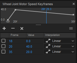
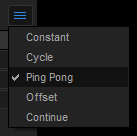
Keyframes can be looped using the Loop Types drop-down button. You can choose between Constant (i.e., no loop), Cycle, Ping Pong, Offset, or Continue. Those loop types are similar to the ones found in AE expressions.
Keyframes can be copied and pasted to another similar property using the Copy/Paste Keyframes commands in the Edit menu. For instance, Density keyframes of a given body can be copied and pasted to other bodies, and Distance Joint Tension keyframes of a given distance joint can be copied and pasted to other distance joints.
Notes:
- Clicking on a keyframe in the graph view (i.e., the small square) opens its value field.
- During a pasting operation, all previous keyframes (if any) are erased before pasting the new ones.
Preferences
Newton's preferences dialog allows you to customize certain aspects of the plug-in, such as the appearance of the user interface, the joint colors, or the behavior of kinematic bodies.
General
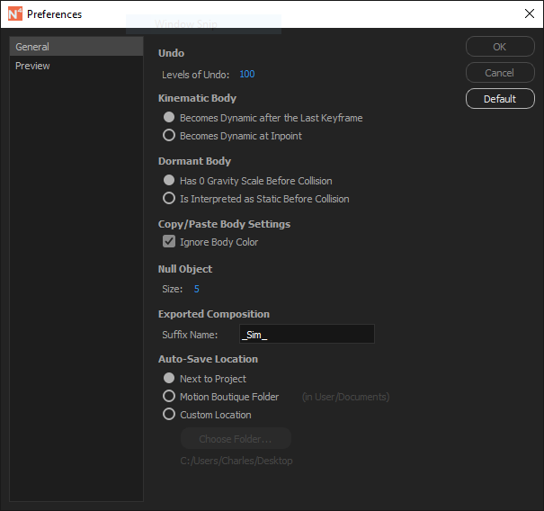
Undo
This parameter specifies the maximum number of undo levels.
Kinematic Body
A kinematic body becomes dynamic after a certain criterion is met. You can choose between Becomes Dynamic after the Last Keyframe and Becomes Dynamic at Inpoint options.
Dormant Body
A dormant body doesn't move until another body collides with it. This option allows you to specify how Newton must interpret a dormant body before a collision occurs. You can choose between Has 0 Gravity Scale before Collision and Is Interpreted as Static before Collision options. The first option tells Newton to interpret dormant bodies as dynamic that are not influenced by gravity. The second option tells Newton to interpret dormant bodies as static bodies. These options yield slightly different simulations when collisions occur.
Copy/Paste Body Settings
You can choose whether the body color is also pasted when pasting body settings.
Null Object Size
This parameter sets the size of null layers.
Exported Composition Suffix Name
This preference sets the name that will be added to the end of the exported composition.
Auto-Save Location
This preference allows you to specify the location of the auto-saved settings file. You can choose between Next to Project, the Motion Boutique folder (in user's Documents folder), or a custom location.
Preview
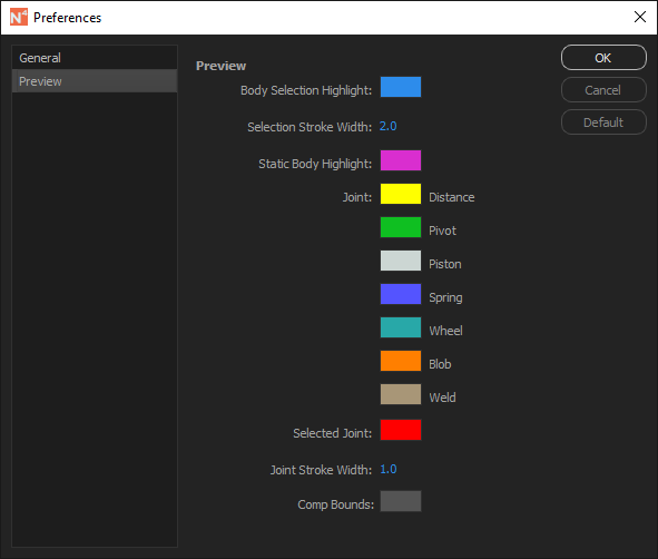
Body Selection Highlight
This parameter sets the color used for highlighting the selected bodies.
Selection Stroke Width
This parameter sets the width of the stroke used for highlighting the selected bodies.
Static Body Highlight
This parameter sets the color used for highlighting static bodies.
Joint Color
This parameter sets the joint color associated with its type.
Selected Joint
This parameter sets the color of the selected joints.
Joint Stroke Width
This parameter sets the width of the stroke used to draw joints.
Comp Bounds
This parameter sets the color used for drawing the bounds of the composition.
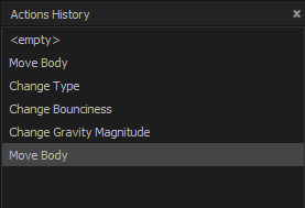
Actions History
You can use the Actions History panel to quickly jump between past operations. To clear history, right-click in the view and choose Clear.
Loading and Saving Settings
Once you have assigned settings to the bodies (including position and rotation), you can save them to a file for future use. You can load previously saved settings using the Load button. Newton uses a custom compressed file format (.nwt) to store the settings. For compatibility reasons, Newton is also able to load the XML settings used in the previous versions.
When you close the main window with the Auto Save option turned on, Newton automatically saves the current scene settings to a file, and writes an identifier in the composition's comment field. When you open Newton and the Auto Load option is turned on, Newton tries to find the appropriate auto-saved settings by looking for an identifier in the composition's comment. If it finds the corresponding file, it automatically applies the settings to the current scene. This auto load/save mecahnism is particularly useful when you need to jump frequently back and forth between Newton and the same composition.
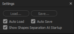
The additional Show Shapes Separation At Startup parameter in the settings panel allows you to enable/disable the Shapes Separation dialog when Newton opens a scene. For instance, if you work on the same composition that contains a multi-shapes layer that you don't want to separate into individual layers, you could turn this option off to prevent the Shapes Separation dialog from opening when Newton starts.
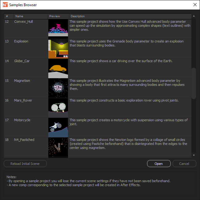
Samples Browser
The Samples Browser dialog can be accessed using the File menu. It allows you to load and inspect demonstration scenes. To load a sample, select it in the list and click on the Open button (or double-click directly on the sample item).
If you want to go back to the original scene, click on the Reload Initial Scene button.
Notes:
- Opening a sample scene will erase the current scene settings. Make sure to save them (using the Save Settings button) if you want to reuse them later.
- When you open a sample scene, the corresponding composition is created in AE and automatically loaded into Newton.
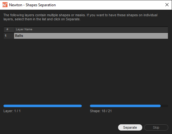
Separating Shapes
When a layer contains more than one mask or path, the Shapes Separation dialog pops up. You must specify whether Newton should interpret each shape of a layer as an individual layer (AE) or body (Newton). If you don't separate shapes, the compound shape will be considered.
Applying Result
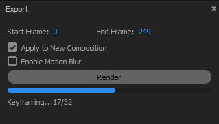
When you are satisfied with the simulation, specify the frame range to be exported and hit Render. By default, the end frame is set to the last frame number of the composition, but you can specify any duration.
Two additional options allow you to specify whether the result must be applied to a copy of the original composition and whether motion blur must be enabled for moving bodies.
The simulation is solved again, but this time animation data are stored in memory. At the end of the simulation, stored values are converted to AE keyframes, and Newton quits.
Note:
- Setting the End Frame in the Export panel also sets the end frame of the preview.
Keyboard Shortcuts
You can open the Keyboard Shortcuts dialog either using the menu command Help > Keyboard Shortcuts... or using Alt+. shortcut. The following table enumerates the available shortcuts.
| Key | Result |
|---|---|
| Setting type of selected bodies | |
| S | Set to static |
| K | Set to kinematic |
| D | Set to dynamic |
| A | Set to dormant |
| M | Set to AEmatic |
| E | Set to dead |
| R | Set to triggermatic |
| Moving/Rotating selected body | |
| ←↑→↓ | Move by 1 pixel |
| Shift ←↑→↓ | Move by 10 pixels |
| + or =/- | Rotate by +1/-1 degree |
| Shift + or Shift =/Shift - or Shift _ | Rotate by +10/-10 degrees |
| Shift + Mouse | Vertical move |
| Alt + Mouse | Horizontal move |
| Selecting bodies | |
| C | Select bodies with the same color |
| L | Select bodies with the same label |
| Q | Select bodies with the same collision group |
| T | Select bodies with the same type |
| I | Invert selection |
| Selecting joints | |
| W | Select joints of selected bodies |
| F | Select similar joints |
| Alt W | Remove selected joints |
| Selecting tools | |
| V | Select the Selection Tool |
| H | Select the Hand Tool |
| Hold down Space Bar or Middle Button | Select temporarily the Hand Tool |
| Y | Select the Joint Anchor Tool |
| G | Select the Gravity Tool |
| P | Select the Velocity Tool |
| Simulation commands | |
| 0 (Num) or Space Bar | Start or Pause |
| Home | Go to first frame |
| 1 (Num)or Page Down | Go to next frame |
| 2 (Num) | Activate loop mode |
| Joint anchors | |
| X | Move AEmatic anchor to center of mass |
| Alt Move | Relative shift of selected AEmatic anchors |
| Move anchorA and anchorB of selected distance joints | |
| Relative shift of selected pivot joints | |
| Move anchorA and anchorB of selected spring joints | |
| Ctrl* Move | Snap anchor to nearest contour vertex |
| Creating distance joints | |
| Shift Click | Cycle (also for pivot and weld joints) |
| Alt Click | Shortest distance |
| Alt Shift Click | Shortest distance on anchorA-anchorB line |
| Ctrl* Alt Click | Between every pair |
| Ctrl* Alt Shift Click | Triangulation |
| Settings | |
| Alt O | Open the Load Settings dialog |
| Alt S | Open the Save Settings dialog |
| Edit menu commands | |
| Ctrl Z (win), Alt Z (mac) | Undo |
| Ctrl Y (win), Alt Shift Z (mac) | Redo |
| Auxiliary dialogs | |
| Ctrl* Alt P | Preferences |
| Alt . | Keyboard Shortcuts |
| Ctrl* Alt Shift R | Randomizer |
| F1 (win), Cmd ? (mac) | User Guide |
| Show or hide panels | |
| Alt 1 (Num) | Bodies |
| Alt 2 (Num) | Joints |
| Alt 3 (Num) | Global Properties |
| Alt 4 (Num) | Body Properties |
| Alt 5 (Num) | Joint Properties |
| Alt 6 (Num) | Export |
| Alt 7 (Num) | Info |
| Alt 8 (Num) | Actions History |
| Ctrl* Alt 1 (Num) | Toggle all |
| Alt 0 (Num) | Reset to default layout |
| Miscellaneous | |
| Alt H | Hide selected bodies |
| Alt U | Unhide all bodies |
| Delete or Backspace | Remove selected scene presets |
| Ctrl* Alt W/X | Increase or decrease line width of selected open shape |
| Z | Reset pan and zoom |
| Ctrl* Alt Q | Exit |
*: Cmd on Mac
Good & Bad Shapes
Newton supports various kinds of shapes, from simple boxes to complex custom curves. However, since the complexity of a shape highly influences the performance of the engine, it is recommended to keep the shapes as simple as possible.
Most of the shapes are first triangulated to obtain a set of convex polygons that are glued together. The more the shape is complex, the more the number of triangles is high. Text shapes for instance may require hundreds of triangles to be represented in Newton, even for a single character.
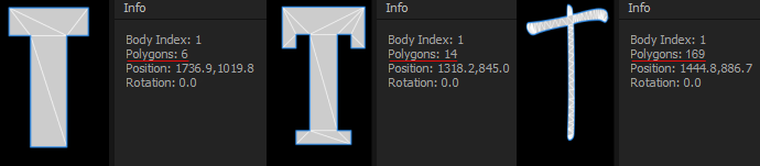
Good shapes are shapes that can be represented by a small number of internal triangles. Typically, this includes shapes created with the Rectangle/Ellipse/Polygon/Star Tool and custom simple paths. Note that rectangles and circles are highly optimized for fast processing, use them whenever it is possible.
On the other side, bad shapes are shapes that contain many rounded segments (fancy characters for instance), or unnecessary interior shapes. Although they are supported by Newton, they may considerably slow down the simulation. When fine details are not needed, use the Convex Hull advanced option to simplify the shape's contour and to get a faster render.
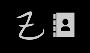
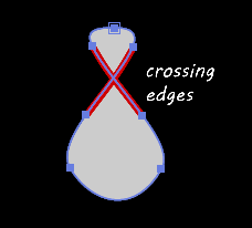
Self-intersecting shapes are not supported by Newton. A self-intersecting shape is a shape whose edges cross each other. When such a case occurs, Newton displays the name and index of the corresponding layers so you can modify them.
Troubleshooting
If you detect a bug or have any questions about Newton, do not hesitate to contact our customer support team.