Description
This script prepares a shape layer (or multiple) for a soft body simulation in Newton. It creates many small solids and places them at regular distance along the shape. It also connects the original shape path to the solids using expression.
After running the script, open Newton and add the appropriate joints to create a soft body. When you are back to AE, the original shape will be automatically modified to follow the animation of the small solids.
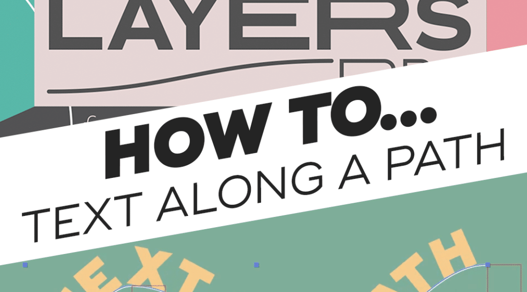
How to… place a text along a path when using our plugin ConnectLayersPRO in Adobe After Effects ?
Good question, here’s the answer!
You need to create a mask on the text layer and link the path of the mask to the path created by ConnectLayersPRO!
This will able you to dynamically change your path using nulls (or other type of layers) as controlers.
Simple and powerfull
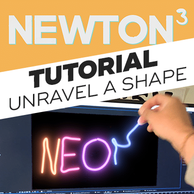
“Hello, is it possible to create the “unraveling” effect on a neon sign that you see at :47 of this video: https://youtu.be/BaLHthRsqQk&t=0m47s “
Well, yeah! It’s possible and here’s how!
In this tutorial, I will show you how to unravel a shape in Adobe After Effects using Newton3 and ConnectLayersPRO.
Here’s the process:
-Track and stabilize with Mocha AE.
-Reverse stabilization.
-Keying using Keylight
-Trace the shape in Adobe Illustrator and export to AE using Overlord
-Prepare the shape for Newton3 using the “Create Nulls from Path” script and ConnectLayersPRO
-Physics simulation with Newton3
-Apply glow with Deep Glow -Final compositing with Composite Brush
I will also use other tools such as: Overlord, MOBO_Utils, Deep Glow and Composite Brush (Note that you can do without these tools).
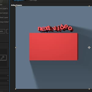
I’ll show you how to quickly set up a simple simulation in Adobe After Effects, send it to Newton3, use fixed objects to only rotate switch and spinners, tweak your scene to have the best result.
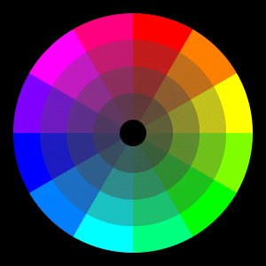
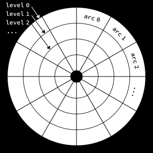
As an exercise to practice our expression coding skills, we would like to create a color wheel using a single shape layer and expressions. The wheel should be made with colored arcs of varying hue, saturation and lightness. We want 4 levels of tint and 12 arcs per level (subdivisions). The following figure shows the different parts of the wheel and the notation we’ll use in the expressions:
Structure of the wheel
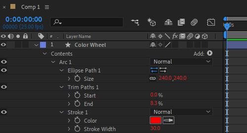
Constructing The Base Arc
We want to create an initial arc, add expressions to it, and then duplicate that arc to construct the entire wheel. The setup consists of a shape group containing a trimmed stroked ellipse:
Setup for the base arc
Since the wheel is made of concentric circles, the size of each circle depends on the level. We apply the following expression to the ellipse size:
The expression is the same for the end property, except the last line:
...
(arcIdx + 1) * (100 / subdivs);
The stroke width is set to 10% of the comp height:
0.1 * thisComp.height;
And finally we apply the following expression to the stroke color:
subdivs = 12;
numLevels = 4;
idx = parseInt(thisProperty.propertyGroup(3).name.split(" ")[1]) - 1;
levelIdx = Math.floor(idx / subdivs);
arcIdx = idx % subdivs;
h = arcIdx / subdivs; // hue
s = 1 - levelIdx / numLevels; // saturation (from high to low)
l = linear(levelIdx, 0, numLevels-1, 0.5, 0.3); // lightness (remap range)
a = 1; // alpha (doesn't affect the result here)
hslToRgb([h,s,l,a]);
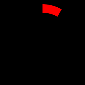
This should produce something like this:
Structure of the wheel
Duplicating The Base Arc
Quite a lot of code for drawing a simple arc, but now comes the fun part. We simply press Ctrl+D (Cmd+D on Mac) to duplicate the base arc until the wheel is complete:
Duplicating the base arc
When the number of arcs reaches 48 (i.e., 4 x 12), the wheel is complete:ession to the ellipse size:
The complete wheel
Reveal Animation
As a bonus we would like to animate the construction of the wheel. To this end, we add a second Trim Paths effector to the base arc (don’t forget to remove every other arc):
Adding a second trim to the base arc
We add the following trim end expression to sequentially reveal the arcs with a short delay:
The expression is the same for the out tangent except the vector points in the opposite direction:
Revealing the wheel
Conclusion
Through this little exercise we have seen how we can manipulate shapes and colors using simple expressions. Hope you find it useful!
You can also check ConnectLayers PRO, a tool that create lines that are dynamically linked to the layers using powerful path expressions. No keyframes at all!
To some extent, Newton 3 reminds me of an open-world video game where the player’s choices can alter what will happen at any given time. While there’s usually a direct start and endpoint for many effects within After Effects, with Newton 3, you can obtain a new result, and thus a new animation, on an infinite scale. I don’t try to be stubborn with my reviews, but I most definitely won’t gloss over the downfalls of a product.
But with Newton 3? I’m just not seeing it. To import several shapes, apply real-world physic simulations with a click of a button, and then render them within a few seconds is a game changer for me. I can’t picture when I wouldn’t use this plugin for most future animations. I’ve had Newton bookmarked for so long that the original bookmark refers to the older version of the plugin. I can only wonder how great my previous videos could have been if I had purchased the plugin sooner.
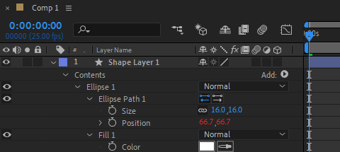
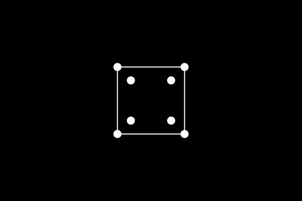
We want to draw the cube vertices with filled ellipses, and connect them with thin stroked lines. We would like to create a single point, apply an expression to its position, and then duplicate that point to create the other points. Once all points are created, we will draw the edges.
Creating the first vertex
Math Utils
Manipulating 3D vectors (rotation, projection) is easier with matrices. Since there aren’t any built-in matrix utilities in the expression language, we must create our own. To avoid having a too long expression, we decide to put our matrix code in an external js file (e.g., “matrix.js”). This file can be imported into our our expression at runtime.
We only need basic stuff here: multiply a matrix and a vector, multiply two matrices… Here is our matrix library:
function vecToMatrix(v)
{
   var m = [];
   for (var i = 0; i < 3; i++)
   {
      m[i] = [];
   }
   m[0][0] = v[0];
   m[1][0] = v[1];
   m[2][0] = v[2];
   return m;
}

function matrixToVec(m)
{
   return [m[0][0], m[1][0], m.length > 2 ? m[2][0] : 0];
}

function matMatMul(a, b)
{
   var colsA = a[0].length;
   var rowsA = a.length;
   var colsB = b[0].length;
   var rowsB = b.length;
   var result = [];
   for (var j = 0; j < rowsA; j++)
   {
      result[j] = [];
      for (var i = 0; i < colsB; i++)
      {
         var sum = 0;
         for (var n = 0; n < colsA; n++)
         {
            sum += a[j][n] * b[n][i];
         }
         result[j][i] = sum;
      }
   }
   return result;
}

function matVecMul(a, v)
{
   var m = vecToMatrix(v);
   var r = matMatMul(a, m);
   return matrixToVec(r);
}
Creating The Vertices
First we need to import the matrix lib (“matrix.js”) into our ellipse position expression. This is done with the following line of code:
$.evalFile("F:/Documents/JSX/matrix.js");
Then we set some design variables and retrieve the index of the cube vertex:
r = 200; // cube size
distance = 2; // affects perspective
rotSpeed = 0.06; // in radians per frame

idx = parseInt(thisProperty.propertyGroup(3).name.split(" ")[1]) - 1;
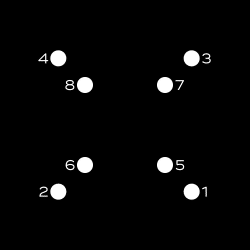
We need to determine the location of each vertex from its index. To do that we can use the following formula (taken from math.stackexchange):
p = []; // 3D vertex position at start
bs = [];
for (i = 0; i < 3; i++)
{
	bs[i] = (idx >> i) & 1;
	p[i] = 0.5 * Math.pow(-1, bs[i]);
}
Note that the above formula will position the vertices in the following order (front face: 1-2-4-3, back face: 5-6-8-7):
Traveling along the path
Now that we have found the 3D starting position of the vertices, we can dive into the main part of this exercise. We basically loop through every previous frame, setup rotation matrices based on the current angle, apply 3 successive rotations (around Y, X, and Z axis), and finally project the 3D vertex to find its 2D position inside the shape layer. Here is the beast:
angle = 0;
for (t = 0; t <= time; t += thisComp.frameDuration)
{
	// rotation matrices (https://en.wikipedia.org/wiki/Rotation_matrix#Basic_rotations)
	rxMatrix = [[1,0,0], [0,Math.cos(angle),-Math.sin(angle)], [0,Math.sin(angle),Math.cos(angle)]];
	ryMatrix = [[Math.cos(angle),0,-Math.sin(angle)], [0,1,0], [Math.sin(angle),0,Math.cos(angle)]];
	rzMatrix = [[Math.cos(angle),-Math.sin(angle),0], [Math.sin(angle),Math.cos(angle),0], [0,0,1]];

	// do rotations (the order matters, here we chose it arbitrarily)
	p3d = matVecMul(ryMatrix, p);
	p3d = matVecMul(rxMatrix, p3d);
	p3d = matVecMul(rzMatrix, p3d);

	// increase rotation angle
	angle += rotSpeed;
}
// handle perspective
z = 1 / (distance - p3d[2]);

// project 3D point
projectionMatrix = [[z, 0, 0], [0, z, 0]];
p2d = matVecMul(projectionMatrix, p3d);

// scale result
mul(p2d, r);
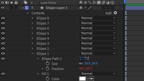
To create the cube vertices we just need to duplicate the first Ellipse group 7 times.
Duplicating the first vertex
We obtain the following animation:
Animating the vertices
Great, our calculations seem correct. Now we need to connect those dots to finish the cube.
Creating The Edges
Since we cannot connect all vertices with a single path, we need to create multiple connecting lines. We want these lines to be constructed from the same unique expression, and control the connected vertices by specifying their indices in the shape’s group name.
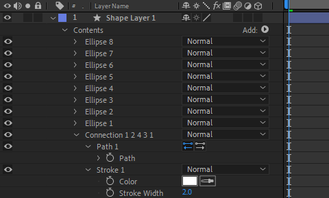
Here is the first connecting path which connects the first four vertices (i.e., the front face):
Creating the first connecting pathEdges of the front face
We apply the following expression to the path property of the connection:
indices = thisProperty.propertyGroup(3).name.split("Connection ")[1].split(" ");
pts = [];
for (i = 0; i < indices.length; i++)
{
	idx = indices[i];
	pt = content("Ellipse " + idx).content("Ellipse Path 1").position;
	pts.push(pt);
}
createPath(pts, [], [], false);
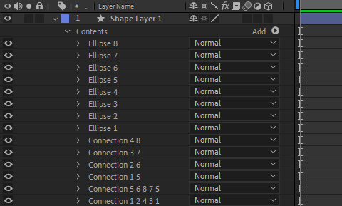
For creating every other connection we duplicate the first connection and rename it with the appropriate indices list for that connection. The final timeline looks like this:
Final timeline
It’s time to press the 0 key on the numpad to preview the final animation.
Spinning cube projected onto a shape layer
Conclusion
In this exercise we have shown how to project a 3D object onto a 2D plane using expressions. We have created our own matrix library to facilitate 3D calculations, and imported it into our expression. We used it to setup and manipulate rotation and projection matrices. Hope you find it useful!
You can also check ConnectLayers PRO, a tool that create lines that are dynamically linked to the layers using powerful path expressions. No keyframes at all!