Introduction
Connect Layers PRO (CLP) is a tool for Adobe After Effects (AE) that allows you to connect composition layers with lines created using shape layers.
CLP provides a simple, clean, and compact creation panel to choose the type of connection. Once the connection is created, you can modify the appearance of the connecting lines using the Styles panel.
CLP requires After Effects CC 2018 or later.
Note:
- The Creation panel is a script. Install it in the ScriptUI Panels folder and execute it via the Window menu.
- The Styles panel is a standard effect plug-in. Install it in the Plug-ins folder. You don't need to apply this effect directly (it doesn't appear in the Effects menu), but you need to install it so the Creation panel can use it.
User Interface
You construct the connection using the Creation panel. Then you modify style settings using the Styles effect.
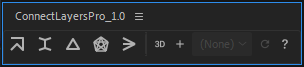
Creation Panel
The Creation panel can be docked everywhere in AE's window. This panel allows you to select the connection type. It also provides additional construction options such as adding new elements to an existing connection.

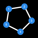
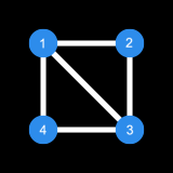
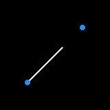
Chain
This command creates a path that connects the selected layers, respecting the order in which layers are selected. Use right-click to create a closed chain.
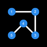

Spanning Tree
This command creates a minimum length tree that spans the distance between the selected layers.


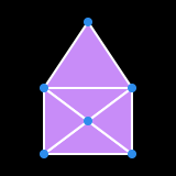
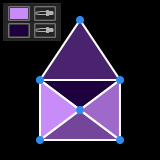
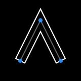
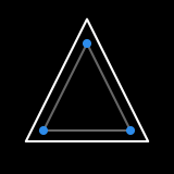
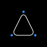
Triangulation
This command creates a Delaunay triangulation from the selected layers.

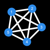
All Connections
This command creates all possible connections between the selected layers.

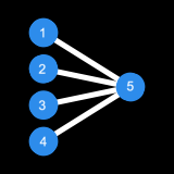
Many-To-One
This command connects the selected layers to the last layer selected.

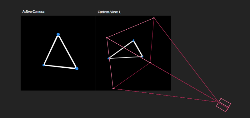
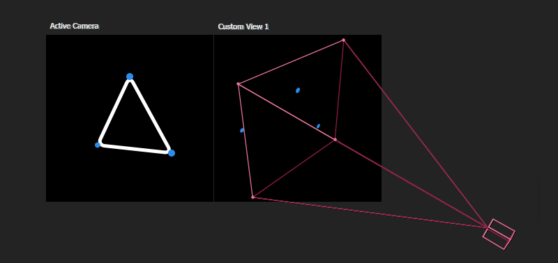
Real 3D Mode
CLP provides two methods to handle 3D layers. The default mode converts 3D layer positions into the camera's view space to create the connections on a 2D layer (therefore it is not visible in Custom View). The second method is the Real 3D mode, which uses the actual 3D layer positions to create the connections on separate 3D layers.
This switch activates the Real 3D mode.
Note:
- The Real 3D mode creates one separate layer per connection segment. The appearance of the segments is controlled by a unique Controller layer.
Add To Existing Connection
This option allows you to add new elements to an existing connection by selecting a composition layer. This is useful when you want to control the style of the new elements with an existing Styles controller.
Note:
- When the Real 3D mode is activated, elements are created on new layers but they share the same Controller.

About and Registration
This button opens the About dialog which contains a description of the tool and the registration info.
Note:
- By default, CLP runs in trial mode. The trial version is limited to 3 layers, and expires within 7 days. To unlock the trial, you need to enter your license code in the registration dialog that pops up when you open CLP.
- You can find your license code in the My Downloads & Licenses section in your user account on aescripts.com.
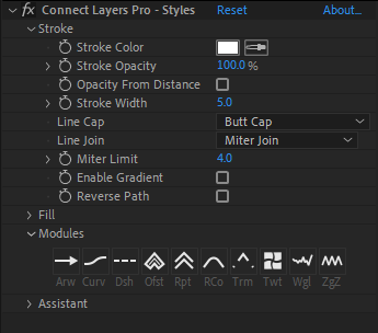
Styles Panel
The CLP Styles effect is automatically added by the Creation panel when you create a connection. With this effect you can control many aspects of the connecting lines, including the stroke and fill options, arrowheads, dashes, and several path operators like trim, twist or zig zag.
Stroke Options
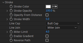
Stroke > Stroke Color
This parameter sets the stroke color of the connection.
Stroke > Stroke Opacity
This parameter controls the stroke transparency.
Stroke > Opacity From Distance
When this parameter is activated, stroke opacity is calculated from the distance between the connected layers. The opacity increases when the distance between the connected layers decreases.
Stroke > Opacity From Distance > Near
This parameter controls the distance (in pixels) from where the stroke opacity is 100%.
Stroke > Opacity From Distance > Far
This parameter controls the distance (in pixels) from where the stroke opacity is 0%.
Stroke > Opacity From Distance > Reverse Behavior
When this parameter is selected, the opacity fading behavior is reversed (0% at Near distance, 100% at Far distance).
Stroke > Stroke Width
This parameter controls the stroke width.
Stroke > Line Cap / Line Join
These parameters control the aspect of the line cap (butt, round, or projecting), as well as the line join (miter, round, or bevel).

Stroke > Miter Limit
When Line Join is set to Miter Join, this parameter controls the miter limit.
Stroke > Enable Gradient
This parameter allows you to add a gradient stroke effect.
Stroke > Gradient Type
This parameter controls the type of the gradient stroke. Yu can choose a Linear or Radial gradient.

Stroke > Highlight Length / Highlight Angle
When the gradient type is set to radial, you can control the highlight length and angle.
Stroke > Gradient Colors > Reveal in Timeline
Use this button to edit the gradient colors.
Stroke > Gradient Scale
This parameter affects the position of the gradient Start/End Points. For a linear gradient, the Start/End Points position is scaled from their middle point. For a radial gradient, the Start Point is not affected by scaling, and the End Point position is scaled from the Start Point.
Stroke > Reverse Direction
This parameter allows you to reverse the direction of the connection.
Fill Options
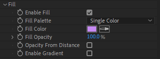
Fill > Enable Fill
Fill is deactivated by default. Use this parameter to enable it.
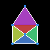
Fill > Fill Palette
This parameter controls the colorization of the connection. You can choose between Single Color, Gradient, Hue Shift, Random, and From Layer, as well as many Adobe Kuler presets.
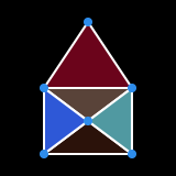
Fill > Fill Color
When Single Color is selected, this parameter sets the fill color of the connection.
Fill > Start / End Color
When Gradient is selected, this parameter sets the start and end color of the gradient.
Fill > Saturation / Luminance
When Hue Shift is selected, these parameters control the intensity of the saturation and luminance.
Fill > Random Seed
When Random is selected, this parameter sets the seed of the random color generator.
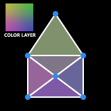
Fill > Color Layer
When From Layer is selected, this parameter allows you to select a composition layer from which color will be sampled.
Fill > Fill Opacity
This parameter controls the fill transparency.
Fill > Opacity From Distance
When this parameter is activated, fill opacity is calculated from the distance between the connected layers.
Fill > Opacity From Distance > Near
This parameter controls the distance (in pixels) from where the fill opacity is 100%.
Fill > Opacity From Distance > Far
This parameter controls the distance (in pixels) from where the fill opacity is 0%.
Fill > Opacity From Distance > Reverse Behavior
When this parameter is selected, the opacity fading behavior is reversed (0% at Near distance, 100% at Far distance).
Fill > Enable Gradient
This parameter allows you to add a gradient fill effect.
Fill > Gradient Type
This parameter controls the type of the gradient fill. You can choose a Linear or Radial gradient.
Fill > Highlight Length / Highlight Angle
When the gradient type is set to radial, you can control the highlight length and angle.
Fill > Gradient Colors > Reveal in Timeline
Use this button to edit the gradient colors.
Fill > Gradient Scale
This parameter affects the position of the gradient Start/End Points. For a linear gradient, the Start/End Points position is scaled from their middle point. For a radial gradient, the Start Point is not affected by scaling, and the End Point position is scaled from the Start Point.
Modules
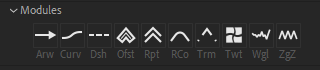
Modules are shape operators that can be enabled or disabled on the fly. Modules include AE's path operators (offset, round corners, wiggle, etc), and some custom effectors like arrowheads or curviness.
To clarify the meaning of the icons, the modules names are displayed in a shortened form under each icon. The following abbreviations are used: Arw (Arrowheads), Curv (Curviness), Dsh (Dashes), Ofst (Offset Paths), Rpt (Repeater), RCo (Round Corners), Trm (Trim Paths), Twt (Twist), Wgl (Wiggle Paths), and ZgZ (Zig Zag).
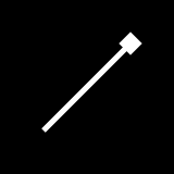
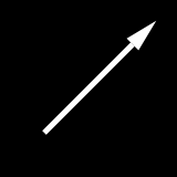
Arrowheads
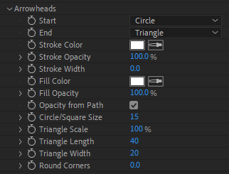
Arrowheads > Start / End
This parameter sets the type of the starting/ending arrowhead. You can choose from None, Circle, Square, and Triangle.

Arrowheads > Stroke Color
This parameter sets the stroke color of the arrowheads.
Arrowheads > Stroke Opacity
This parameter sets the stroke transparency of the arrowheads.
Arrowheads > Stroke Width
This parameter sets the stroke width of the arrowheads.
Arrowheads > Fill Color
This parameter sets the fill color of the arrowheads.
Arrowheads > Fill Opacity
This parameter sets the fill transparency of the arrowheads.
Arrowheads > Opacity from Path
When this parameter is active, the arrowheads opacity (both stroke and fill) is inherited from the stroke opacity of the path.
Arrowheads > Circle / Square Size
When Start or End is set to Circle or Square, this parameter controls the size in pixels of the arrowheads.
Arrowheads > Triangle Scale
When Start or End is set to Triangle, this parameter sets the global scale of the triangle.
Arrowheads > Triangle Length
When Start or End is set to Triangle, this parameter sets the length of the triangle.
Arrowheads > Triangle Width
When Start or End is set to Triangle, this parameter controls the width of the triangle.
Arrowheads > Round Corners
This parameter allows you to round the corners of the arrowheads.
Curviness
Function
This parameter controls the formula used to calculate the curviness of the connection. The default is Linear, which produces a straight connection line.
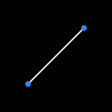
Curviness > Linear
The connection is formed by a straight line.
Curviness > Arc
The connection is formed by a circular arc.
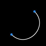
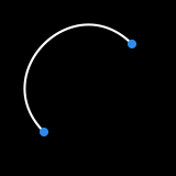
Arc > Flip Direction
This parameter sets the arc orientation (towards the inside or outside).
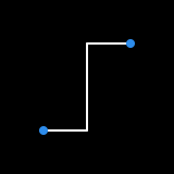
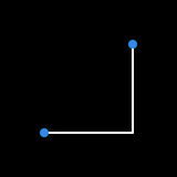
Curviness > Step / Step After / Step Before (2D only)
The connection is formed by a step-like shape.
Curviness > Auto Bezier Tension
The connection is formed by a Bezier path that passes through the selected layers. The tension at each vertex is similar to AE's RotoBezier.
Curviness > Custom Bezier Tension
The connection is formed by a Bezier path with customizable tension.
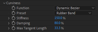
Curviness > Dynamic Bezier
The connection is formed by a Bezier path whose tangents vary over time according to the velocity of the connected layers.
Curviness > Dynamic Bezier > Preset
When a dynamic function is selected (Dynamic Bezier for instance), this parameter allows you to select predefined settings.


Curviness > Dynamic Bezier > Stiffness
This parameter sets the connection stiffness.
Curviness > Dynamic Bezier > Damping
This parameter controls the damping of the connection.
Curviness > Dynamic Bezier > Max Tangent Length
This parameter allows you to restrict the influence of velocity on the distortion of the tangents.
Curviness > Custom Dynamic Bezier
This connection is similar to Dynamic Bezier, but you can also define custom tangents for the connection path. It supports only two layers (i.e., a single connection segment).
Curviness > Dynamic Verlet
The connection is formed by a chain of dynamic subsegments. A process of iterative constraint enforcement is imposed on these subsegments until a solution is found. This method requires heavy calculations. It must be used with care (for example over a short duration) as the evaluation time increases quickly and may become unmanageable as the comp time increases.
Curviness > Dynamic Verlet > Preset
When Dynamic Verlet is selected, this parameter allows you to select predefined settings.


Curviness > Dynamic Verlet > Stiffness
This parameter allows you to control the stiffness of the connection.
Curviness > Dynamic Verlet > Solver Steps
This parameter specifies the number of iterations of the constraint solver. A low number will usually produce acceptable results.
Curviness > Dynamic Verlet > Subsegments
This parameter defines the number of vertices of the connection path.
Curviness > Dynamic Verlet > Gravity
This parameter controls the gravity amplitude. Gravity is always directed towards the bottom of the screen.
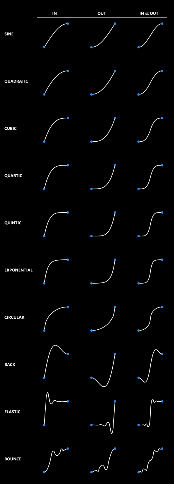
Curviness > Penner's Easing Functions
The connection is formed by a path that follows one of the Robert Penner's Easing Functions.
Penner's Functions > Precision
This parameter controls the number of vertices of the connection path.
Penner's Functions > Angle (3D only)
This parameter affects the orientation of the connection path.
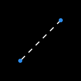
Dashes
This module adds AE Dashes to the connection, and allows you to control the effect settings directly from the effect panel.
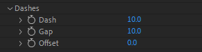
Dashes > Dash
This parameter controls the length of the dashes.
Dashes > Gap
This parameter controls the gap between dashes.
Dashes > Offset
This parameter controls the offset of the pattern along the path.
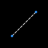
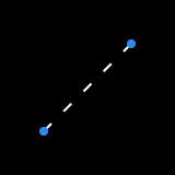
Offset Paths
This module adds AE Offset Paths to the connection, and allows you to control the effect settings directly from the effect panel.
Offset > Amount
This parameter controls the offset from the original path.
Repeater
This module adds AE Repeater to the connection, and allows you to control the effect settings directly from the effect panel.
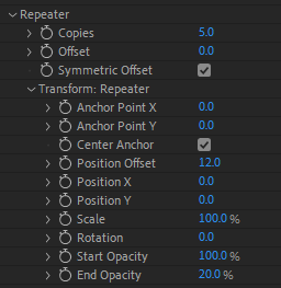
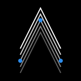
Repeater > Copies
This parameter controls the number of copies of the original path.
Repeater > Offset
This parameter sets a global offset from the original path.
Repeater > Symmetric Offset
This parameter forces the copies to be symmetrically distributed around the original path.
Repeater > Transform
These parameters affect the transformation of each copy individually. This includes the anchor point, position, scale, and rotation properties.
Repeater > Start Opacity
This parameter controls the transparency of the first copy.
Repeater > End Opacity
This parameter controls the transparency of the last copy.
Round Corners
This module adds AE Round Corners to the connection, and allows you to control the effect settings directly from the effect panel.
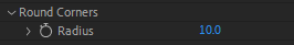
Round Corners > Radius
This parameter controls the roundness radius.
Trim Paths
This module adds AE Trim Paths to the connection, and allows you to control the effect settings directly from the effect panel.
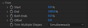
Trim > Start
This parameter controls the start point of the path, expressed as percentage of the original path.
Trim > End
This parameter controls the end point of the path.
Trim > Both Ends
This parameter controls both the start and end points of the path.
Trim > Offset
This parameter controls the offset along the original path.
Trim > Trim Multiple Shapes
This parameter controls whether multiple shapes are trimmed simultaneously or individually.
Twist
This module adds AE Twist to the connection, and allows you to control the effect settings directly from the effect panel.
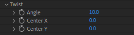
Twist > Angle
This parameter controls the twist angle in degrees.
Twist > Center X/Y
This parameter sets the center point of the twist effect.
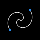
Wiggle Paths
This module adds AE Wiggle Paths to the connection, and allows you to control the effect settings directly from the effect panel.
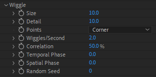
Wiggle > Size
This parameter controls the amplitude of the distortion.
Wiggle > Detail
This parameter sets the density of the jagged edges.
Wiggle > Points
This parameter controls whether the corner points are sharp or smooth.
Wiggle > Wiggles/Second
This parameter controls the amount of the wiggle.
Wiggle > Correlation
This parameter specifies the amount of similarity between the movement of a vertex and that of its neighbors.
Wiggle > Temporal/Spatial Phase
This parameter controls the variation of wiggle.
Wiggle > Random Seed
This parameter sets the seed of the random number generator.
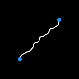
Zig Zag
This module adds AE Zig Zag to the connection, and allows you to control the effect settings directly from the effect panel.
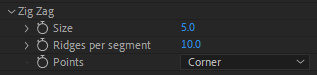
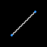
Zig Zag > Size
This parameter controls the amplitude of the peaks and valleys.
Zig Zag > Ridges per segment
This parameter sets the number of ridges per path segment.
Zig Zag > Points
This parameter controls whether corner points are sharp or smooth.
Note:
- Since AE's Zig Zag effect starts and ends at a peak or a valley, arrowheads (if selected) won't be properly attached to the extremities of the modified path.
Assistant
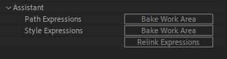
Path Expressions > Bake Work Area
This command converts all path expressions into keyframes. The composition work area determines the start/end times of the keyframing.
Style Expressions > Bake Work Area
This command converts all style expressions to keyframes.
Relink Expressions
This command re-enables baked expressions.
A Note About Performance
CLP makes an intensive usage of expressions. AE CC 2019 has introduced a new expression engine called "Javascript", which is generally faster than the old one (now called "Legacy ExtendScript"). This is the default engine and we do recommend you to use it.
The current selected engine can be found in the Project Settings dialog (in the the Expressions tab). To open this dialog, click on File > Project Settings, or use the dedicated (rocket) button next to the Create New Comp button.
.Known Issues
- When using gradients with the Real 3D mode, the "Reveal in Timeline" button in the effect panel will cause AE to crash. Use the equivalent button in the timeline instead.
Troubleshooting
If you have any questions about this tool, do not hesitate to contact our customer support team.